I. Basic Definition and Classification
1. Core Concept
PID, short for **Potential Induced Degradation**, refers to a phenomenon where the performance of solar cells deteriorates continuously due to ion migration triggered by the potential difference between internal materials of PV modules under long-term high-voltage bias. First systematically proposed by SunPower in 2005, it is a core issue affecting the long-term reliability of PV modules.
2. Main Types (Classified by Degradation Mechanism)
| Type | Abbreviation | Core Characteristics | Impact Level | Reversibility |
|---|
| Power Attenuation Type | PID-P | The most common type; sodium ion migration damages anti-reflection coatings and pn junctions, reducing parallel resistance | Severe (power loss up to 30%) | Partially reversible |
| Short-Circuit Current Attenuation Type | PID-S | Degradation of the passivation layer on the cell surface, increasing carrier recombination | Moderate | Reversible |
| Open-Circuit Voltage Attenuation Type | PID-V | Mainly affects n-type cells, reducing minority carrier lifetime | Mild | Reversible |
II. Core Mechanism: Ion Migration is the Key
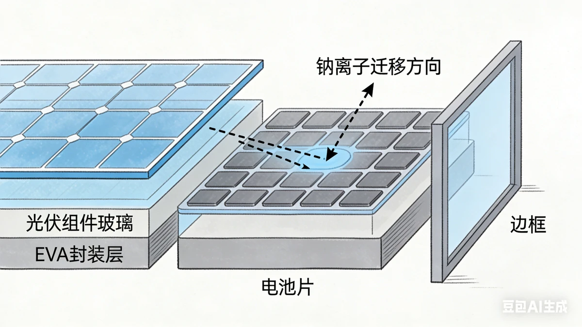
The essence of the PID effect is **electric field-driven ion migration and leakage current formation**, with the complete process as follows:
Establishment of Potential Difference:After the module frame is grounded, a high voltage difference (usually 1000-1500V systems) is formed between solar cells and the frame.
Formation of Conductive Channels:- Moisture absorption by encapsulation materials (e.g., EVA) in high-humidity environments (or condensation) forms a conductive medium required for ion migration.
Ion Migration:Under negative bias, mobile ions such as **sodium ions (Na?)** in glass and encapsulation materials migrate toward the cell surface.
Performance Degradation:Sodium ions accumulate on the surface of the cell's anti-reflection layer (SiN?), damaging the passivation effect and resulting in:
- Decreased parallel resistance and increased leakage current
- Reduction in fill factor (FF), open-circuit voltage (Voc), and short-circuit current (Isc)
- Ultimately, significant attenuation of the module's maximum power (Pmax)
III. Key Influencing Factors (Three Essential Conditions for Occurrence)
Voltage Conditions(Necessary Condition):The higher the negative bias voltage of the module relative to the ground, the more significant the PID effect; generally, the more modules in series (higher system voltage), the greater the risk.
**Environmental Conditions(Accelerating Condition):
- Humidity: Ion migration rate increases sharply when relative humidity exceeds 60%
- Temperature: The PID rate approximately doubles for every 10°C increase; attenuation is fastest at 85°C
Module-Specific Factors:
- Encapsulation Materials: Early EVA is prone to moisture absorption with poor PID resistance; POE materials perform better
- Glass Type: Ordinary soda-lime glass contains a large amount of sodium ions; low-sodium glass can reduce risks
- Cell Type: p-type cells are more sensitive to PID, while n-type cells (e.g., TOPCon, HJT) have stronger PID resistance
- Encapsulation Process: Lamination quality and edge sealing directly affect moisture intrusion
IV. Hazards and Impacts
- Power Generation Loss**: 10%-30% module power attenuation directly impacts the power plant's IRR (Internal Rate of Return)
- Service Life Reduction: Long-term PID effect may cause irreversible damage such as hot spots and microcracks in modules
- Increased Operation and Maintenance Costs: Additional resources need to be invested in testing, repair, and even module replacement
- Safety Risks: Increased leakage current may cause local overheating of modules, posing fire hazards
V. Testing Methods and Standards
1. Laboratory Testing (Factory Verification)
IEC TS 62804-1 標準: Specifies three testing methods to evaluate the PID resistance of modules
- Dark-State Testing: Apply negative bias voltage (typically -1000V) to modules and maintain them in an 85℃/85%RH environment for 96 hours
- Light-State Testing: Simulate actual operating conditions to evaluate PID effect under illumination
Power Attenuation Criterion: A Pmax attenuation rate ≤ 5% before and after testing is considered qualified, and ≤ 2% is excellent
2. On-Site Testing (Power Plant Operation and Maintenance)
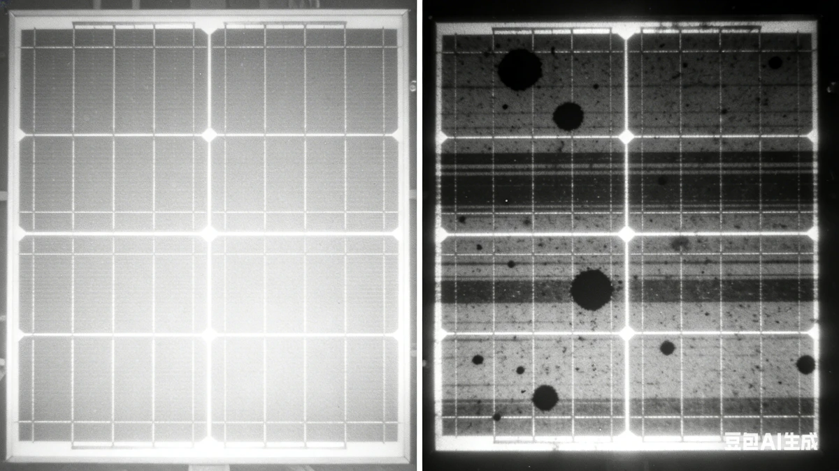
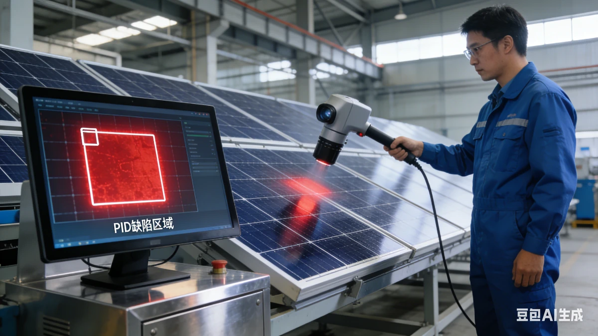
- EL (Electroluminescence) Testing: EL images of PID-affected modules showblack spots/streaks,corresponding to leakage current areas
- IV Curve Testing: Compare the actual Pmax of modules with the nominal value to calculate the attenuation rate
- Leakage Current Monitoring: Install leakage current sensors to real-time monitor the leakage current of modules to the ground (normal value < 10μA)
- Thermal Imaging Testing: Severe PID areas generate local overheating due to leakage current, which can be detected as abnormal hot spots via thermal imaging
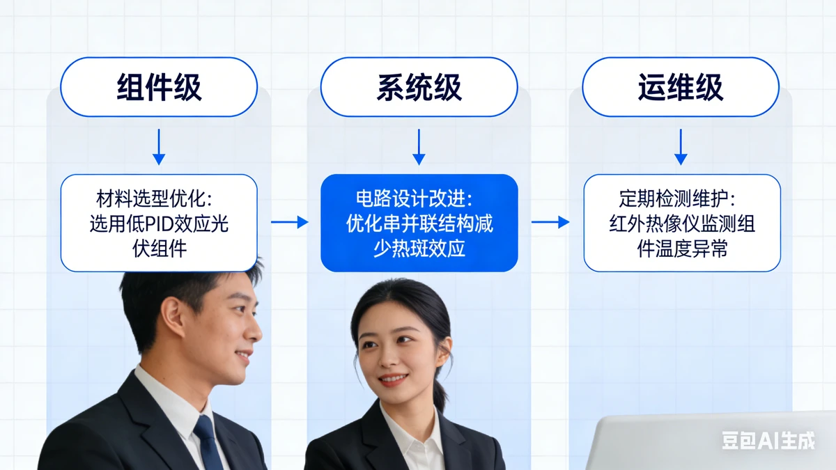
VI. Solutions and Prevention and Control Strategies (Three-Level Prevention and Control System)
1. Module-Level Prevention and Control (Source Treatment)
- Adoptlow-sodium glassOptimize cell passivation processes to enhance surface resistance to ion contaminationPID-resistant encapsulation materials(e.g., POE/EVA blend films)
- Optimize cell passivation processes to enhance surface resistance to ion contamination
- Addmoisture-proof sealing layers at module edges to reduce moisture intrusion
- Conduct PID preconditioning(e.g., positive bias aging) before factory shipment to activate PID resistance performance
2. System-Level Prevention and Control (Design Optimization)
| Technical Solution | Working Principle | Applicable Scenarios |
|---|
| Positive Grounding of Modules | Eliminates negative bias voltage of solar cells, fundamentally preventing ion migration | Newly built power plants, suitable for p-type modules |
| PID Restorers | Apply reverse voltage (+1000V) at night to move migrated ions back | Existing power plants with reversible PID |
| System Voltage Optimization | Reduce the number of series-connected modules to lower system voltage (e.g., from 1500V to 1000V) | Power plants in high-humidity areas |
| Frame Insulation Treatment | Add insulation layers between frames and module interiors to reduce leakage current | Distributed power plants with space constraints |
3. Operation and Maintenance-Level Prevention and Control (Long-Term Guarantee)
- Regular Testing**: Conduct combined EL + IV + thermal imaging testing every 6-12 months to identify early-stage PID modules
- Environmental Monitoring: Deploy temperature and humidity sensors in power plants and strengthen inspections during high-risk periods (plum rain season, summer)
- Timely Repair: Use restorers to treat lightly affected PID modules and replace severely attenuated modules promptly
- Cleaning and Maintenance: Regularly clean module surfaces to reduce local potential differences caused by dust accumulation
VII. Application of Machine Vision in PID Detection
As a manufacturer of photovoltaic inspection equipment, Shichuang Intelligence can provide the following PID-specific inspection solutions:
- AI-EL Automatic Detection System**: Automatically identify PID features (black spots/streaks) with high-resolution EL imaging and deep learning algorithms, achieving a detection accuracy of over 99%
- Online PID Monitoring Equipment: Integrate leakage current sensors and thermal imaging modules to real-time monitor module PID status and provide early warnings
PID Repair Effect Verification System: Compare EL images and IV curves before and after repair to quantify repair effectiveness (power recovery rate)
VIII. Industry Trends and Conclusion
- Technological Evolution: Thanks to structural advantages, n-type cells (TOPCon, HJT) have significantly better PID resistance than p-type cells and have become the mainstream in the future
- Standard Upgrade: IEC 62804-1:2025 adds light-state testing methods, which are more in line with actual operating conditions
- Cost Optimization: The cost of PID-resistant materials decreases year by year and has become a standard configuration for modules (market share > 90% in 2025)